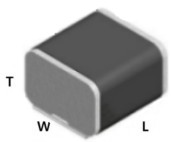
Overview
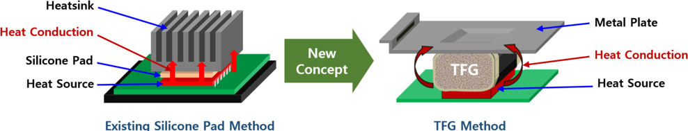
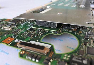
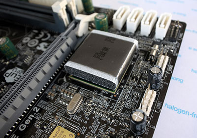
- Thermal Foam Gasket(TFG) is a thermally conductive foam gasket with a graphite surface with excellent horizontal thermal conductivity. It transfers heat from the heat source (CPU, GPU, etc.) to the heatsink or metal plate over a short time, spreading heat widely and lowering the temperature of the heat source.
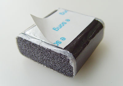
- Heat-resistant urethane foam is applied as core material to improve resilience and adhesion and minimize weight.
- It has a wide range of use without thickness restriction, unlike existing silicone gap pads.
- Compared to the existing silicone gap pad method
Features
- Used graphite with excellent horizontal thermal conductivity (400W/mK)
- The graphite surface is entirely covered with PET film to prevent particles from graphite.
- Due to its excellent elasticity and moderate pressure on PCB, there is less chance of bending PCB.
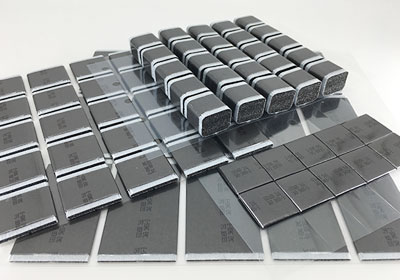
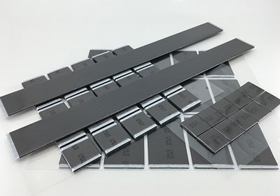
- Various sizes and shapes can be manufactured according to the application, and heat conductivity and hardness are adjustable.
- Holding several related patents
Details
Specification
Test product size: Width 30mm, Length 30mm, Thickness 3mm
| Contents |
Unit |
Data |
Remarks |
| Thermal Conductivity |
W/mK |
>2 |
ASTM C 518, ASTM E 1530-06 |
| Surface Resistance |
Ω/□ |
>1x10⁸ |
ESQ-612-04 |
| Tracking-Resistivity |
V |
<105 |
K 30112, CTI |
| Withstanding Voltage |
V |
<1000 |
ASTM D 149 |
| Operating Temperature |
℃ |
<120 |
ESQ-612-20 |
| Flame Retardancy |
UL94V-0 (E221431) |
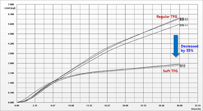
Compression force comparison (Soft TFG)
Regular TFG and Soft TFG have no difference in performance, such as thermal conductivity and surface resistance. Still, the yield strength of Soft TFG is about 55% lower compared to Regular TFG, which allows Soft TFG to be applied on PCB boards of soft materials or to prevent damage due to high compression force between internal parts.
| Compression Force |
Regular TFG |
Soft TFG |
| 10% |
2.3 kgf |
1.9 kgf |
| 20% |
4.3 kgf |
2.3 kgf |
| 30% |
5.9 kgf |
2.6 kgf |
* Test sample: Width 32mm, Length 28mm, Thickness 10.5mm
Thermal conductivity comparison with existing silicone pad
- Sample size of TFG and Silicone pad: 28(W) x 32(L) x 10.5(T)
- Measure the temperature change after pressing the specimen 20% between the heating plates.
- After heating the lower heating plate to 150℃ and laying the specimen on the lower heating plate, measure the time until the thermal sensor of the upper heating plate rises from the initial setting value of 40℃ to 60℃.
| Type |
Thermal Conductivity |
Average Reaching Time |
| TFG |
>2 W/mK |
70” |
| Silicone Pad |
2 W/mK |
166” |
| 3 W/mK |
69” |
| 5 W/mK |
60” |
※ Advantages of TFG compared to silicon thermal pad
- Silicone pads have siloxanes that harden after prolonged usage, but TFG is free from siloxane generation.
- Silicone pads have a poor compressive restoring force which may reduce the adhesion. Still, TFG uses a high-resilience sponge and has an excellent compressive restoring force that the adhesion is steady over time.
- Silicone pads tend to harden over time which can cause PCB to bend. There is little concern about PCB warpage due to its lightweight and excellent elasticity.
- TFG is often lighter than silicone pads when the gap between the heat source and sink is large.
Array setting for better thermal conduction
Optimal heat conduction system for a large area for effective heat dissipation
Characteristic
- The graphite sheet effectively dissipates the heat energy of the heat source and transmits it to the heatsink, suppressing the temperature rise of the target device.
- Heat-resisting polyurethane sponge provides good compression resilience.
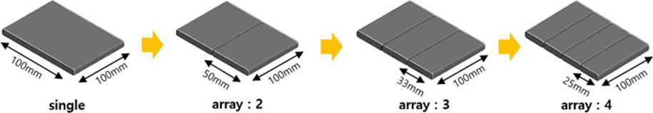
- The heat transfer efficiency increases for the same size as the number of arrays increases.
- Easy to manufacture in various sizes.
Performance test results
[Test Conditions]
- 100mm (W) x 100mm (L) x 3mm (T) samples by array number.
- The temperature of the hot upper plate and lower measuring part were set to 150℃ and 35℃.
- The sample was placed between the top and bottom and was compressed by 20%.
- It measures the time the upper row is transferred to the lower measuring unit through the sample and reaches a specific temperature. (the time from the temperature of the lower measuring part to 40℃ to getting 60℃)
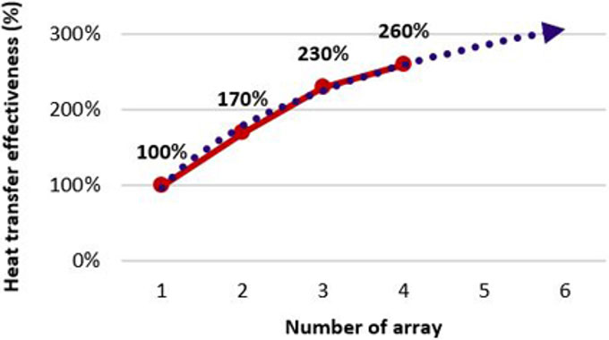
[Test Results]
Compared to a single type without an array, the results show that as the number of arrays increases to 2, 3, 4, etc., the efficiency of heat conduction increases.
| Number of Array |
Heat conduction comparison test result (Sec.) |
| Sample #1 |
Sample #2 |
Sample #3 |
Sample #4 |
Sample #5 |
Average
|
| 1 |
120.4 |
125.1 |
120.9 |
124.3 |
122.1 |
122.6 |
| 2 |
73.4 |
74.2 |
72.6 |
71.9 |
72.5 |
72.9 |
| 3 |
53.4 |
54.8 |
55.2 |
51.9 |
53.4 |
53.7 |
| 4 |
47.4 |
49.7 |
48.1 |
47.2 |
46.1 |
47.7 |
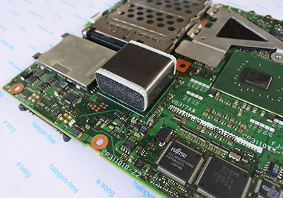
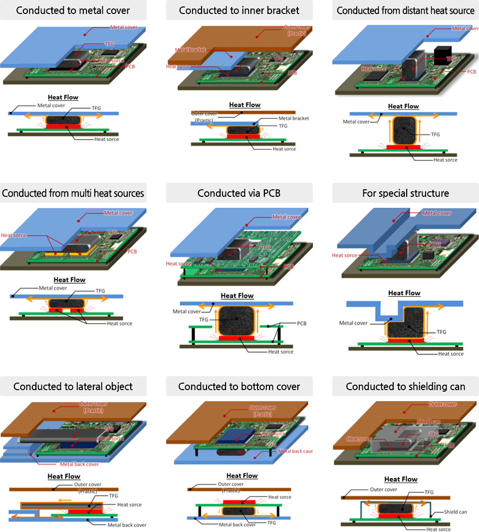
Applications
TFG transfers heat from the heat source to the heatsink or metal plate to prevent overheating.
Versatile Applications
Product Support
Product Number
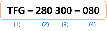
| Number |
Code |
Example |
| (1) |
Product Code |
TFG: Thermal foam gasket |
| (2) |
Width (W) |
280: 28.0mm |
| (3) |
Length (L) |
300: 30.0mm |
| (4) |
Thickness (T) |
080: 8.0mm |